

Locating eMMC Test Points PullOFF
Locate and Desolder eMMC Chip
Locate and Desolder eMMC Chip You must always remove the eMMC chip from a board identical to your exhibit. Never attempt this process on your exhibit.
The first step is to locate the eMMC chip on your board. If in doubt then Google the chip model numbers.
The eMMC chip has been circled in the image below.
You will need to use a hot air gun or suitable rework station to desolder and remove this chip. This is a BGA (Ball Grid Array) chip, meaning that all of the contacts are on the bottom. You will not be able to access them until the chip is removed
Under the Chip
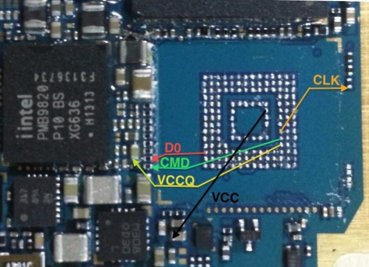
After the chip is removed you will see the ball grid array as in the photo below.
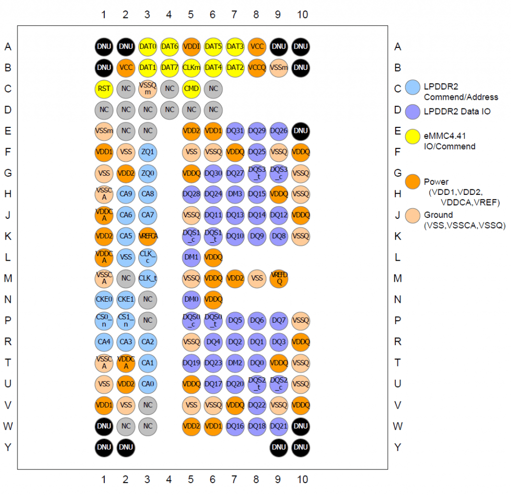
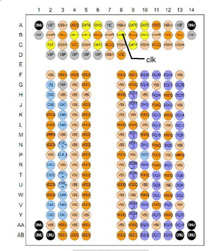
These points are all defined in the eMMC standard and are displayed below
Connections Of the points on the chip, the ones of interest to us are:
- DAT0 (Data transfer BiDirectional Line)
- CMD (Commands transfer BiDirectionl Line )
- CLK ( Clock Lane)
- Vcc ( eMMC Core Power usually 2.85V )
- VccQ ( eMMC IO Power usually 1.8V )
- Vss (Commonly known as GND)
You will find more than one Vcc, VccQ and Vss. It does not matter which one you use. Using a continuity tester, place one probe on each of the exposed points on the board listed above and touch each of the components on the board until the continuity tester indicates you have a direct connection.
Vss should be easily located as any RF Shield or Shield Frame if you have removed the shield. On some boards Vcc and VccQ are directly connected. Once a component has been located that connects to each of the points above then note it (best on a high quality photograph of the board). You should now have all of the points identified but there is one more step before you can extract data with EasyJTAG.
Determining the Correct Voltages
You have identified Vcc and VccQ but you need to confirm the voltages that you need to supply to them. To do this you need a working board. It is not recommended to use the exhibit for this, but a second test model. Leaving the eMMC chip in place, apply power to the board either from the battery of the device or the power supply and turn the device on. Apply a voltmeter between Vcc and GND and note the voltage, it will probably be 3.3v. Apply a voltmeter between VccQ and GND and note the voltage. It is usually 3.3v or 1.8v. If you previously identified that Vcc and VccQ were directly connected then you will note they both require the same voltage and when using EasyJTAG you can extract using 5 wires . If the Vcc and VccQ voltages are different then you will need to use 6 wires and the ISP-voltage adapter.